Above: Alternative approaches to linking multiple floors in plan
For more complex buildings and settings, it may be necessary to link analysis across multiple floors or areas of space. The Isovist_App allows for this to be done by means of user defined ‘linkers’, which affect the spatial analysis field results accordingly. To define linker objects:
- Open the ‘Drawing and Setup menu’.
- Select ‘Edit Scan Settings’, followed by the ‘Set Spatial Links’ option.
- At this point, the view should highlight the areas that have been selected for analysis in magenta. Linker objects must start and end within the magenta regions.
- On the drawing on screen, click in the location that a link is required to start from, and a ringed dot will appear in dark purple.
- Move the cursor, and click again at the location that the link is required to end. A second ringed dot should appear, along with a linking line that represents the linker object.
- To delete a linker object, hover the cursor over the small purple dot at the centre of the link line. When changes to orange, click the cursor and the linker will be deleted.
- Once linkers have been set, the preview can be closed by clicking on any other menu option.
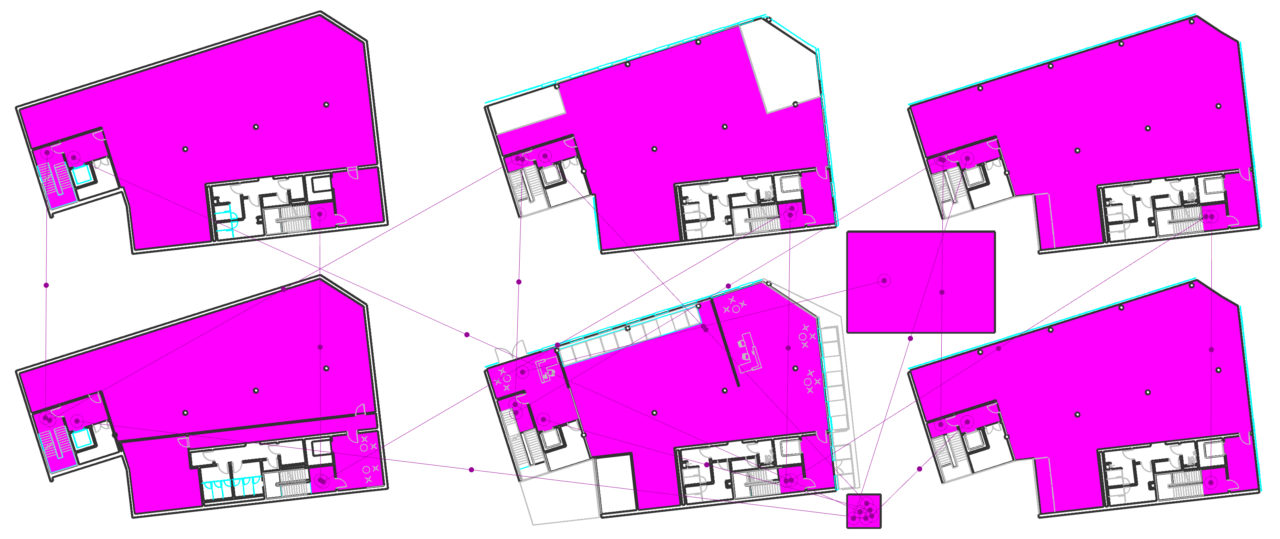
Above: Setting up a multi floor plan; areas for analysis in magenta, and floor to floor links shown in purple.